Tuesday 26 February 2013

Catalytic converter

What is a catalytic converter and how does it work? 

A catalytic converter is a device that uses a catalyst to convert three harmful compounds in car exhaust into harmless compounds.

The three harmful compounds are:
  • Hydrocarbons (in the form of unburned gasoline)
  • Carbon monoxide (formed by the combustion of gasoline)
  • Nitrogen oxides (created when the heat in the engine forces nitrogen in the air to combine with oxygen)
http://static.ddmcdn.com/gif/catalytic-converter-location.jpg
Carbon monoxide is a poison for any air-breathing animal. Nitrogen oxides lead to smog and acid rain, and hydrocarbons produce smog.
In a catalytic converter, the catalyst (in the form of platinum and palladium) is coated onto a ceramic honeycomb or ceramic beads that are housed in a muffler-like package attached to the exhaust pipe. The catalyst helps to convert carbon monoxide into carbon dioxide. It converts the hydrocarbons into carbon dioxide and water. It also converts the nitrogen oxides back into nitrogen and oxygen.

http://www.cateran.com.au/cateran/images/technical.jpg
Most commonly used in an automobile's exhaust system, catalytic converters are now commonly used on generator sets, forklifts, mining equipment, trucks, buses, trains, and other machines that have engines to provide an environment for a chemical reaction where unburned hydrocarbons are more completely combusted.

http://completeautomotive417.com/wp-content/uploads/2011/08/Catalytic_Converter.jpg.opt677x480o00s677x480.jpg
Catalytic converters are still most commonly used in exhaust systems in automobiles, but are also used on generator sets, forklifts, mining equipment, trucks, buses, locomotives, motorcycles, airplanes and other engine-fitted devices.

Types

Two-way

A two-way (or "oxidation") catalytic converter has two simultaneous tasks:
  1. Oxidation of carbon monoxide to carbon dioxide: 2CO + O2 → 2CO2
  2. Oxidation of hydrocarbons (unburnt and partially burnt fuel) to carbon dioxide and water: CxH2x+2 + [(3x+1)/2] O2 → xCO2 + (x+1) H2O (a combustion reaction)
This type of catalytic converter is widely used on diesel engines to reduce hydrocarbon and carbon monoxide emissions. They were also used on gasoline engines in American- and Canadian-market automobiles until 1981. Because of their inability to control oxides of nitrogen, they were superseded by three-way converters.

http://autotech4rent.com/home/wp-content/uploads/2011/11/catalytic-photo.jpg

Three-way

Since 1981, "three-way" (oxidation-reduction) catalytic converters have been used in vehicle emission control systems in the United States and Canada; many other countries have also adopted stringent vehicle emission regulations that in effect require three-way converters on gasoline-powered vehicles. The reduction and oxidation catalysts are typically contained in a common housing, however in some instances they may be housed separately. A three-way catalytic converter has three simultaneous tasks:
https://blogger.googleusercontent.com/img/b/R29vZ2xl/AVvXsEgIyqng0GF0iIeFgP0qSDYoTwypA_S8kZAAsxEfPHC34O2I07Q1h_Z4Q7MAvDCopAXwNaLOFtXSOmrtBguNdklo4tYj27vrIP3IBxvwAQahr-1VNlQf0Hdr4xdg9lB7tipbM6IoSqBI0kuX/s1600/catalytic+converter.jpg
  1. Reduction of nitrogen oxides to nitrogen and oxygen: 2NOx → xO2 + N2
  2. Oxidation of carbon monoxide to carbon dioxide: 2CO + O2 → 2CO2
  3. Oxidation of unburnt hydrocarbons (HC) to carbon dioxide and water: CxH2x+2 + [(3x+1)/2]O2 → xCO2 + (x+1)H2O.

Actuator

An actuator is something that converts energy into motion. It also can be used to apply a force. An actuator typically is a mechanical device that takes energy — usually energy that is created by air, electricity or liquid — and converts it into some kind of motion. That motion can be in virtually any form, such as blocking, clamping or ejecting. Actuators typically are used in manufacturing or industrial applications and might be used in devices such as motors, pumps, switches and valves.
Perhaps the most common type of actuator is powered b
y air and is called a pneumatic cylinder or air cylinder. 
http://www.spiraxsarco.com/images/resources/steam-engineering-tutorials/6/6/fig6.6.01.gif
An actuator also can be powered by electricity or hydraulics. Much like there are air cylinders, there also are electric cylinders and hydraulic cylinders in which the cylinder converts electricity or hydraulics into motion. Hydraulic cylinders, which use liquids, are often found in certain types of vehicles.
. An actuator is the mechanism by which a control system acts upon an environment. The control system can be simple (a fixed mechanical or electronic system), software-based (e.g. a printer driver, robot control system), or a human or other agent.

http://www.wordsun.com/assets/raw-2-1184330585.jpg

Types of Motion

Actuators can create a linear motion, rotary motion or oscillatory motion. That is, they can create motion in one direction, in a circular motion or in opposite directions at regular intervals. Hydraulic and air cylinders can be classified as single-acting cylinders, meaning that the energy source causes movement in one direction and a spring is used for the other direction.
http://www.mathworks.com/help/physmod/hydro/ref/dbl_act_valve_act2.gif
                                                      HYDRAULIC ACTUATORS

Muscles as Actuators

Although actuators typically are discussed in terms of mechanical implements, muscles are sometimes given as an example of actuators. Energy is converted by the muscle into motion. For example, the calories that are in food that a person consumes represent energy that can be used by his or her muscles — which act as actuators — to create motion, such as running, kicking a ball or dancing.

Sensors AND Transducers

Sensors can be broadly classified in two categories: discrete event and continuous. Discrete event, or on/off sensor, changes its state based on the occurrence of some external event. These sensors typically only give knowledge of two states based on the condition being sensed. They are based on mechanical, electrical or optical technology. Continuous sensors provide information over the continuous range of operation of the process and are commonly used in continuous control applications, where the process is being regulated based on continuously sensed attribute data. They are based on electrical, optical and acoustical technologies.
http://www.opengeospatial.org/pub/www/files/images/SWE%20Overview_0.jpg

ACTIVE AND PASSIVE SENSORS

The sensors can be classified as active and passive. A passive sensor has no power supply and all the energy it delivers to the next stage (the signal conditioning) is drawn from the measurand. Passive sensors are also known as self-generating sensors. An active sensor is a modulator and can therefore deliver more energy to the next stage than it draws from the measurand. If the power supply is dc, the output is modulated by the measurand, and has the same frequency. If the supply is ac, the output is the carrier frequency with sidebands at signal frequency.
https://blogger.googleusercontent.com/img/b/R29vZ2xl/AVvXsEhUFtGCOuHW9tU2vtTEYRtKBGdn1oMrWYcM6PocuuAyW1nEFgY8a-U3rgzAPlHNpePfuOowgOqtWOzVUFAICDbqwgL05u7c4v5Bf8Qq8d8sox2Q9ojNH1Zigk4wWHdyCcEUibFcoZsmzsc/s1600/Capacitor+Pressure+Transducer.JPG

BASIC REQUIREMENTS OF A SENSOR/TRANSDUCER

A transducer is normally designed to sense a specific measurand or to respond only to that
particular measurand. A complete knowledge of the electrical and mechanical
characteristics of the transducer is of great importance while choosing a transducer for a
particular application. Often, it is deemed essential to get details of these characteristics
during the selection of instrumentation for the experiment concerned. The basic
requirements are : 

Ruggedness

Ability to withstand overloads, with safety stops for overload protection.

 Linearity

Ability to reproduce input-output characteristics symmetrically and linearly.
Overall linearity is the main factor considered.

 Repeatability

Ability to reproduce the output signal exactly when the same measurand is
applied repeatedly under same environmental conditions.

 Convenient Instrumentation

Sufficiently high analog output signal with high signal to noise ratio; digital

TRANSDUCERS

A useful way to classify transducers is on the basis of the physical property the device is intended to measure. The important properties discussed in this section are :
 Position
 Velocity
 Force or Pressure
 Temperature

 Position Transducers

Position transducers are widely used in servomotors, linear position tables, and other applications where prices position is important. In this section we will discuss four analog position transducers (potentiometers, linear variable differential transformers, floats and resolvers) and two digital position transducers (the optical encoder and ultrasonic range sensor).
http://www.puiaudio.com/images/whitepaper_transducer_circuit1.jpg

Velocity Transducers

Velocity transducers are used for speed control. We shall describe the digital (optical
encoder) and analog (DC tachometer) velocity transducers.
Force or Pressure Transducers
Force sensors are used extensively in automatic weighing operation in the process
industries and in robotic applications when it is necessary to control gripping pressure. In
this section we shall examine two analog transducers: the load cell and the strain gage.

Load Cells

A load cell is used in processes where precise weighing is required. It can be
implemented using a strain gage or a LVDT. Illustrates a load cell
implemented by using a LVDT and a spring with linear force displacement relation.

Electromagnetic clutches

Electromagnetic clutches and brakes seem simple, but complex variations fit them to multiple applications.

Electromagnetic clutches operate electrically but transmit torque mechanically. Engineers once referred to them as electromechanical clutches. Over the years EM came to stand for electromagnetic, referring to the way the units actuate, but their basic operation has not changed.
The electromagnetic clutch is most suitable for remote operation since no linkages are required to control its engagement. It has fast, smooth operation. However, because energy dissipates as heat in the electromagnetic actuator every time the clutch is engaged, there is a risk of overheating.
http://magnetic-clutch.com/assets/images/clutch-internal.jpg


Elements of EM
Both EM clutches and brakes share basic structural components: a coil in a shell, also referred to as a field; a hub; and an armature. A clutch also has a rotor, which connects to the moving part of the machine, such as a driveshaft.
The coil shell is usually carbon steel, which combines strength with magnetic properties. Copper wire forms the coil, although sometimes aluminum is used. A bobbin or epoxy adhesive holds the coil in the shell.
Magnetic and friction forces accelerate the armature and hub to match rotor speed. The rotor and armature slip past each other for the first 0.02 to 1.0 sec until the input and output speeds are the same. The matching of speeds is sometimes called 100% lockup.

How it works

Engagement

When the clutch is required to actuate, current flows through the electromagnet, which produces a magnetic field. The rotor portion of the clutch becomes magnetized and sets up a magnetic loop that attracts the armature. The armature is pulled against the rotor and a frictional force is generated at contact. Within a relatively short time, the load is accelerated to match the speed of the rotor, thereby engaging the armature and the output hub of the clutch.

Disengagement

When current is removed from the clutch, the armature is free to turn with the shaft. In most designs, springs hold the armature away from the rotor surface when power is released, creating a small air gap.
http://upload.wikimedia.org/wikipedia/commons/5/54/B-1_electromagnetic-clutch1.gif

Cycling

Cycling is achieved by interrupting the current through the electromagnet. Slippage normally occurs only during acceleration. When the clutch is fully engaged, there is no relative slip, assuming the clutch is sized properly, and thus torque transfer is 100% efficient.

Applications

Machinery
Automobiles
Locomotives

Applications in automobile

When the electromagnetic clutch is used in automobiles, there may be a clutch release switch inside the gear lever. The driver operates the switch by holding the gear lever to change the gear, thus cutting off current to the electromagnet and disengaging the clutch. With this mechanism, there is no need to depress the clutch pedal. Alternatively, the switch may be replaced by a touch sensor or proximity sensor which senses the presence of the hand near the lever and cuts off the current. The advantages of using this type of clutch for automobiles are that complicated linkages are not required to actuate the clutch, and the driver needs to apply a considerably reduced force to operate the clutch. It is a type of semi-automatic transmission.

Monday 25 February 2013

steering system

You know that when you turn the steering wheel in your car, the wheels turn. Cause and effect, right? But a lot of interesting stuff goes on between the steering wheel and the tires to make this happen.
In this article, we'll see how the two most common types of c­ar steering systems work: rack-and-pinion and recirculating-ball steering. Then we'll examine power steering and find out about some interesting future developments in steering systems, driven mostly by the need to increase the fuel efficiency of cars.


http://fireonroad.com/wp-content/uploads/2013/01/STEERING-SYSTEM.jpg

Introduction

Steering is the term applied to the collection of components, linkages, etc. which will allow a vessel (ship, boat) or vehicle to follow the desired course.

Wheeled vehicle steering

The basic aim of steering is to ensure that the wheels are pointing in the desired directions. This is typically achieved by a series of linkages, rods, pivots and gears. One of the fundamental concepts is that of caster angle - each wheel is steered with a pivot point ahead of the wheel; this makes the steering tend to be self-centering towards the direction of travel.
http://fireonroad.com/wp-content/uploads/2013/01/Parts-of-the-Steering-System.gif


Rack and pinion

The rack and pinion design has the advantages of a large degree of feedback and direct steering "feel". A disadvantage is that it is not adjustable, so that when it does wear and develop lash, the only cure is replacement.

http://www.monroe.com.au/uploads/images/tech_info_images/Steering%20Systems3.gif


The recirculating ball version of this apparatus reduces the considerable friction by placing large ball bearings between the teeth of the worm and those of the screw; at either end of the apparatus the balls exit from between the two pieces into a channel internal to the box which connects them with the other end of the apparatus, thus they are "recirculated".
http://2.bp.blogspot.com/-Z7NWBSLzc3g/TwBR9ISQeGI/AAAAAAAAAjA/P9NhlXKR8n4/s1600/steering.jpg
The worm and sector was an older design, used for example in Willys and Chrysler vehicles, and the Ford Falcon (1960s).

Power steering

http://www.infovisual.info/05/img_en/073%20Hydraulic%20steering%20system.jpg
Power steering helps the driver of a vehicle to steer by directing some of the its power to assist in swivelling the steered roadwheels about their steering axes. As vehicles have become heavier and switched to front wheel drive, particularly using negative offset geometry, along with increases in tire width and diameter, the effort needed to turn the wheels about their steering axis has increased, often to the point where major physical exertion would be needed were it not for power assistance.

Four-wheel steering

Four-wheel steering (or all-wheel steering) is a system employed by some vehicles to improve steering response, increase vehicle stability while maneuvering at high speed, or to decrease turning radius at low speed.

http://firetrucksandequipment.tpub.com/TM-5-4210-220-12/img/TM-5-4210-220-12_28_1.jpg

Crab steering

Crab steering is a special type of active four-wheel steering. It operates by steering all wheels in the same direction and at the same angle. Crab steering is used when the vehicle needs to proceed in a straight line but under an angle (i.e. when moving loads with a reach truck, or during filming with a camera dolly), or when the rear wheels may not follow the front wheel tracks.

Passive rear wheel steering

Many modern vehicles offer a form of passive rear steering to counteract normal vehicle tendencies. On many vehicles, when cornering, the rear wheels tend to steer slightly to the outside of a turn, which can reduce stability. The passive steering system uses the lateral forces generated in a turn (through suspension geometry) and the bushings to correct this tendency and steer the wheels slightly to the inside of the corner. This improves the stability of the car, through the turn.

Rear wheel steering

ear wheel steering tends to be unstable because in turns the steering geometry changes hence decreasing the turn radius (oversteer), rather than increase it (understeer). A rear wheel steered automobile exhibits non-minimum phase behavior.
http://www.hsomerville.com/meccano/images/4ws1.jpg

Safety

For safety reasons all modern cars feature a collapsible steering column (energy absorbing steering column) which will collapse in the event of a heavy frontal impact to avoid excessive injuries to the driver. Airbags are also generally fitted as standard. Non-collapsible steering columns fitted to older vehicles very often impaled drivers in frontal crashes, particularly when the steering box or rack was mounted in front of the front axle line, at the front of the crumple zone.

Watercraft steering

http://www.freepatentsonline.com/7156034-0-large.jpg
Ships and boats are usually steered with a rudder. Depending on the size of the vessel, rudders can be manually actuated, or operated using a servomechanism, or a trim tab/servo tab system. Boats using outboard motors steer by rotating the entire drive unit. Boats with inboard motors sometimes steer by rotating the propeller pod only


Saturday 23 February 2013

Stress–strain curve

The relationship between the stress and strain that a particular material displays is known as that material's Stress-Strain curve.
Stress-strain curves of various materials vary widely, and different tensile tests conducted on the same material yield different results, depending upon the temperature of the specimen and the speed of the loading.
It is possible, however, to distinguish some common characteristics among the stress-strain curves of various groups of materials and, on this basis, to divide materials into two broad categories; namely, the ductile materials and the brittle materials.

http://nptel.iitm.ac.in/courses/Webcourse-contents/IIT-ROORKEE/strength%20of%20materials/lects%20&%20picts/image/lect12/fig%201.jpg

Tensile Stress

 Taking this concept over, we say that the bar is under tension, and is experiencing a stress that we define to be the ratio of the force to the cross sectional area.Stress = F/A This stress is called the tensile stress because every part of the object is subjected to a tension.

Ductile materials

Low carbon steel generally exhibits a very linear stress–strain relationship up to a well defined yield point .
The actual rupture point is in the same vertical line as the visual rupture point. However, beyond this point a neck forms where the local cross-sectional area decreases more quickly than the rest of the sample resulting in an increase in the true stress .

http://upload.wikimedia.org/wikipedia/commons/8/84/Stress_Strain_Ductile_Material.png
As shown in Fig.2, On an engineering stress–strain curve this is seen as a decrease in the apparent stress. However if the curve is plotted in terms of true stress and true strain the stress will continue to rise until failure.
Less ductile materials such as aluminum and medium to high carbon steels do not have a well-defined yield point.There are generally two types of yield points,upper and lower yield point.
For these materials the yield strength is typically determined by the "offset yield method", by which a line is drawn parallel to the linear elastic portion of the curve and intersecting the abscissa at some arbitrary value .

Brittle materials

Brittle materials, which includes cast iron, glass, and stone, are characterized by the fact that rupture occurs without any noticeable prior change in the rate of elongation.One of the characteristics of a brittle failure is that the two broken parts can be reassembled to produce the same shape as the original component as there will not be a neck formation like in the case of ductile materials. 
http://nuclearpowertraining.tpub.com/h1017v1/img/h1017v1_70_5.jpg
.

Nozzle

 A nozzle is often a pipe or tube of varying cross sectional area, and it can be used to direct or modify the flow of a fluid.

Types

Jet

A gas jet, fluid jet, or hydro jet is a nozzle intended to eject gas or fluid in a coherent stream into a surrounding medium.

http://www.jshumidifiers.com/images/gallery/JetSpray-nozzle-captioned.gif

High velocity

A de Laval nozzle has a convergent section followed by a divergent section and is often called a convergent-divergent nozzle .
Thus the speed reached at a nozzle throat can be far higher than the speed of sound at sea level. This fact is used extensively in rocketry where hypersonic flows are required, and where propellant mixtures are deliberately chosen to further increase the sonic speed.

http://www.sono-tek.com/wp-content/uploads/2011/12/3-impact.png
Divergent nozzles slow fluids, if the flow is subsonic, but accelerate sonic or supersonic fluids.
Convergent-divergent nozzles can therefore accelerate fluids that have choked in the convergent section to supersonic speeds. This CD process is more efficient than allowing a convergent nozzle to expand supersonically externally.

Propelling

A jet exhaust produces a net thrust from the energy obtained from combusting fuel which is added to the inducted air. This hot air is passed through a high speed nozzle, a propelling nozzle which enormously increases its kinetic energy.

For a given mass flow, greater thrust is obtained with a higher exhaust velocity, but the best energy efficiency is obtained when the exhaust speed is well matched with the airspeed. However, no jet aircraft can maintain velocity while exceeding its exhaust jet speed, due to momentum considerations.
They thus employ simple convergent nozzles. In addition, bypass nozzles are employed giving even lower speeds.
http://brendanflynn.files.wordpress.com/2011/01/turbojet_operation-_axial_flow.png
Rocket motors use convergent-divergent nozzles with very large area ratios so as to maximise thrust and exhaust velocity and thus extremely high nozzle pressure ratios are employed.

Spray

Air-Aspirating Nozzle-uses an opening in the cone shaped nozzle to inject air into a stream of water based foam to make the concentrate "foam up".
http://www.buchi.com/fileadmin/user_upload/01_products/04_spray_drying/img/Nozzle.jpg

Levers and Fulcrums

A lever is a machine consisting of a beam or rigid rod pivoted at a fixed hinge, or fulcrum. It is one of the six simple machines identified by Renaissance scientists.
In this case, the power into the lever equals the power out, and the ratio of output to input force is given by the ratio of the distances from the fulcrum to the points of application of these forces. This is known as the law of the lever.

http://cnx.org/content/m23853/latest/Picture%201.png
The mechanical advantage of a lever can be determined by considering the balance of moments or torque , T, about the fulcrum, where M1 is the input force to the lever and M2 is the output force.
The mechanical advantage of the lever is the ratio of output force to input force, This relationship shows that the mechanical advantage can be computed from ratio of the distances from the fulcrum to where the input and output forces are applied to the lever.
http://www.sciencebuddies.org/Files/3216/5/Phys_img081.jpg

It is common to call the input force the effort and the output force the load or the resistance. This allows the identification of three classes of levers by the relative locations of the fulcrum, the resistance and the effort: Class 1: Fulcrum in the middle: the effort is applied on one side of the fulcrum and the resistance on the other side, for example, a crowbar or a pair of scissors .

These cases are described by the mnemonic "fre 123" where the fulcrum is in the middle for the 1st class lever, the resistance is in the middle for the 2nd class lever, and the effort is in the middle for the 3rd class lever.
http://www.clear.rice.edu/elec201/Book/images/levers.gif
If a and b are distances from the fulcrum to points A and B and let the force FA applied to A is the input and the force FB applied at B is the output, the ratio of the velocities of points A and B is given by a/b, so we have the ratio of the output force to the input force, or mechanical advantage, is given by This is the law of the lever, which was proven by Archimedes using geometric reasoning.
It shows that if the distance a from the fulcrum to where the input force is applied is greater than the distance b from fulcrum to where the output force is applied , then the lever amplifies the input force. On the other hand, if the distance a from the fulcrum to the input force is less than the distance b from the fulcrum to the output force, then the lever reduces the input force.

http://www.constructionknowledge.net/general_technical_knowledge/images_gen_tech_knowledge/lever%20figure%201_3.gif
Thus, the ratio of the output force FB to the input force FA is obtained as which is the mechanical advantage of the lever. This equation shows that if the distance a from the fulcrum to the point A where the input force is applied is greater than the distance b from fulcrum to the point B where the output force is applied, then the lever amplifies the input force.

http://www.engquest.org.au/Images/Machines/SM_diagram5.jpg
If the opposite is true that the distance from the fulcrum to the input point A is less than from the fulcrum to the output point B, then the lever reduces the magnitude of the input force. This is the law of the lever, which was proven by Archimedes using geometric reasoning.

Friday 22 February 2013

Couplings

An improvised flexible coupling made of car tire pieces connects the drive shafts of an engine and a water pump. This one is used to cancel out misalignment and vibrations.
A coupling is a device used to connect two shafts together at their ends for the purpose of transmitting power.
http://www.conveyorchains.in/images/flexi_cone_couplings2.gif

Couplings do not normally allow disconnection of shafts during operation, however there are torque limiting couplings which can slip or disconnect when some torque limit is exceeded.

Types

Rigid

A rigid coupling is a unit of hardware used to join two shafts within a motor or mechanical system.
A rigid coupling may also be added between shafts to reduce shock and wear at the point where the shafts meet.
When joining shafts within a machine, mechanics can choose between flexible and rigid couplings.
While flexible units offer some movement and give between the shafts, rigid couplings are the most effective choice for precise alignment and secure hold.

They generally are large enough so that screws can pass all the way through the coupling and into the second half to ensure a secure hold.Flanged rigid couplings are designed for heavy loads or industrial equipment.
Rigid couplings are used when precise shaft alignment is required; shaft misalignment will affect the coupling's performance as well as its life.
http://www-mdp.eng.cam.ac.uk/web/library/enginfo/textbooks_dvd_only/DAN/motors/steady/couplingsABIG.jpg
A clamp coupling is different from the sleeve coupling in that the sleeve used in this type is split from one side.The shafts are entered and keyed to this sleeve and then split sides are screwed together.

Flexible

Flexible couplings are used to transmit torque from one shaft to another when the two shafts are slightly misaligned.
A beam coupling, also known as helical coupling, is a flexible coupling for transmitting torque between two shafts while allowing for angular misalignment, parallel offset and even axial motion, of one shaft relative to the other. This design utilizes a single piece of material and becomes flexible by removal of material along a spiral path resulting in a curved flexible beam of helical shape.
Since it is made from a single piece of material, the Beam Style coupling does not exhibit the backlash found in some multi-piece couplings.

Gear

A gear coupling is a mechanical device for transmitting torque between two shafts that are not collinear .
Gear couplings are generally limited to angular misalignments, i.e., the angle of the spindle relative to the axes of the connected shafts, of 4-5°.
Single joint gear couplings are also used to connected two nominally coaxial shafts.

Oldham

An Oldham coupling has three discs, one coupled to the input, one coupled to the output, and a middle disc that is joined to the first two by tongue and groove .

http://motionsystemdesign.com/images/Flexural-couplings1195.jpg
Requirements of good shaft alignment / good coupling setup it should be easy to connect or disconnect the coupling. it does allow some misalignment between the two adjacent shaft rotation axes. it is the goal to minimise the remaining misalignment in running operation to maximise power transmission and to maximise machine runtime . it should have no projecting parts. it is recommended to use manufacturer's alignment target values to set up the machine train to a defined non-zero alignment, due to the fact that later when the machine is at operation temperature the alignment condition is perfect
Coupling maintenance is generally a simple matter, requiring a regularly scheduled inspection of each coupling.
Checking and changing lubricant regularly if the coupling is lubricated. This maintenance is required annually for most couplings and more frequently for couplings in adverse environments or in demanding operating conditions.
The only way to improve coupling life is to understand what caused the failure and to correct it prior to installing a new coupling.

Keys

In mechanical engineering, a key is a machine element used to connect a rotating machine element to a shaft. The key prevents relative rotation between the two parts and enables torque transmission. For a key to function, the shaft and rotating machine element must have a keyway, also known as a keyseat, which is a slot or pocket the key fits in.

Types of keys

Sunk keys: Type of sunk keys: Rectangular,Square,Parallel sunk,Gib-head,Feather,Woodruff.
Square keys are used for smaller shafts and rectangular faced keys are used for shaft diameters over 6.5 in or when the wall thickness of the mating hub is an issue.
The keyway in a shaft for a parallel key
The main advantage of the Woodruff key is that it eliminates milling a keyway near shaft shoulders, which already have stress concentrations .
The keyway in the hub has a taper that matches that of the tapered key.
A "Scotch key" or "Dutch key" also provides a keyway not by milling but by drilling axially into the part and the shaft, so that a round key can be used.

Keyseating can be done on a variety of different machines including a keyseater, a vertical slotting machine, a broacher, either a vertical or horizontal mill, or with a chisel and file.
The specific broach, bushing and guide are used for each given keyway cross-section, which makes this process more expensive than most of the alternatives. However, it can produce the most accurate keyway out of all the processes.
http://www.accessscience.com/loadBinary.aspx?filename=395200FG0010.gif
There are three main steps in broaching a keyway: First, the workpiece is set on the arbor press and the bushing is placed in the opening of the workpiece.
Keyseaters, also known as keyseating machines and keyway cutters, are specialized machines designed to cut keyways.
Parallel, tapered, and Woodruff keyways can be produced on a milling machine .
End mills or slotting cutters are used for parallel and tapered keyways, while a Woodruff cutter is used for Woodruff keyways.
The keyway is roughed out using a chisel and then filed to size; the key is tried frequently to avoid over filing. This technique is long, tedious, and rarely used anymore.
 

Clutch

http://www.eaton.com/ecm/groups/public/@pub/@eaton/@truck/documents/content/pct_325400.jpg
A clutch is a mechanical device that provides for the transmission of power from one component to another when engaged, but can be disengaged.

Friction clutches

In a pull type clutch, the action of pressing the pedal pulls the release bearing, pulling on the diaphragm spring and disengaging the vehicle drive.
Multiple plate clutch This type of clutch has several driving members interleaved or "stacked" with several driven members.
Since the surfaces of a wet clutch can be slippery , stacking multiple clutch discs can compensate for the lower coefficient of friction and so eliminate slippage under power when fully engaged.
The Hele-Shaw clutch was a wet clutch that relied entirely on viscous effects, rather than on friction.
A centrifugal clutch is used in some vehicles and also in other applications where the speed of the engine defines the state of the clutch, for example, in a chainsaw . This clutch system employs centrifugal force to automatically engage the clutch when the engine rpm rises above a threshold and to automatically disengage the clutch when the engine rpm falls low enough.

The system involves a clutch shoe or shoes attached to the driven shaft, rotating inside a clutch bell attached to the output shaft.
http://www.classicmotorcycles.org.uk/b50/images/technical/b50_clutch_plates.jpg
In the case of a chainsaw this allows the chain to remain stationary whilst the engine is idling; once the throttle is pressed and the engine speed rises, the centrifugal clutch engages and the cutting chain moves.
Torque limiter Also known as a slip clutch or safety clutch, this device allows a rotating shaft to slip when higher than normal resistance is encountered on a machine.

application

There are different designs of vehicle clutch but most are based on one or more friction discs pressed tightly together or against a flywheel using springs .
Clutches found in heavy duty applications such as trucks and competition cars use ceramic clutches that have a greatly increased friction coefficient. However, these have a "grabby" action generally considered unsuitable for passenger cars.
http://www.dansmc.com/hon70atc_clutch.jpg
The spring pressure is released when the clutch pedal is depressed thus either pushing or pulling the diaphragm of the pressure plate, depending on type. However, raising the engine speed too high while engaging the clutch causes excessive clutch plate wear.
Engaging the clutch abruptly when the engine is turning at high speed causes a harsh, jerky start. This kind of start is necessary and desirable in drag racing and other competitions, where speed is more important than comfort. This plastic pilot shaft guide tool is used to align the clutch disk as the spring-loaded pressure plate is installed.

In a modern car with a manual transmission the clutch is operated by the left-most pedal using a hydraulic or cable connection from the pedal to the clutch mechanism.
If the engine is running with clutch engaged and the transmission in neutral, the engine spins the input shaft of the transmission, but no power is transmitted to the wheels.
The clutch is located between the engine and the gearbox, as disengaging it is required to change gear. Although the gearbox does not stop rotating during a gear change, there is no torque transmitted through it, thus less friction between gears and their engagement dogs.
Clutches in typical cars are mounted directly to the face of the engine's flywheel , as this already provides a convenient large diameter steel disk that can act as one driving plate of the clutch.
The propeller shaft between front and rear rotates continuously as long as the engine is running, even if the clutch is disengaged or the transmission is in neutral.
Motorcycles typically employ a wet clutch with the clutch riding in the same oil as the transmission.
A set of coil springs or a diaphragm spring plate force the plates together when the clutch is engaged.
No pressure on the lever means that the clutch plates are engaged , while pulling the lever back towards the rider disengages the clutch plates through cable or hydraulic actuation, allowing the rider to shift gears or coast.

Other clutches—such as for an air conditioning compressor—electronically engage clutches using magnetic force to couple the driving member to the driven member.
Electromagnetic clutch are, typically, engaged by an electromagnet that is an integral part of the clutch assembly.

Another type, magnetic particle clutches, contain magnetically influenced particles in a chamber between driving and driven members—application of direct current makes the particles clump together and adhere to the operating surfaces.
Overrunning clutch or freewheel : If some external force makes the driven member rotate faster than the driver, the clutch effectively disengages.
http://www.zf.com/media/media/img_1/brands_1/sachs/products_sachs/clutches_sachs/clutch_kit_600x570_CV_SACHS.jpg
An oscillating member where this clutch can then convert the oscillations into intermittent linear or rotational motion of the complimentary member; others use ratchets with the pawl mounted on a moving member
The winding knob of a camera employs a wrap-spring type as a clutch in winding and as a brake in preventing it from being turned backwards.
The rotor drive train in helicopters uses a freewheeling clutch to disengage the rotors from the engine in the event of engine failure, allowing the craft to safely descend by autorotation.
Rotating the driving member the other way makes the spring wrap itself tightly around the driving surface and the clutch locks up.

Specialty clutches and applications

Single-revolution clutch

If the trip mechanism is operated when the clutch would otherwise disengage the clutch remains engaged.
When the sleeve's tooth contacted the pawl the sleeve and the load's inertia unwrapped the spring to disengage the clutch.

When the clutch locked up the driven mechanism coasted and its inertia rotated the disc until a tooth on it engaged a pawl that kept it from reversing.

Cascaded-pawl single-revolution clutches

http://www.indiaspiders.net/tractorclutchplate.com/images/clutch-plate2_big.JPG
These superseded wrap-spring single-revolution clutches in page printers, such as teleprinters , including the Teletype Model 28 and its successors, using the same design principles.
Inside the hollow disc-shaped housing were two or three freely floating pawls arranged so that when the clutch was tripped, the load torque on the first pawl to engage created force to keep the second pawl engaged, which in turn kept the third one engaged.
As the clutch rotated it would stay locked up if the trip lever were out of the way, but if the trip lever engaged the clutch would quickly unlock.

Welding

Welding is a fabrication or sculptural process that joins materials, usually metals or thermoplastics , by causing coalescence . This is often done by melting the workpieces and adding a filler material to form a pool of molten material that cools to become a strong joint, with pressure sometimes used in conjunction with heat , or by itself, to produce the weld. This is in contrast with soldering and brazing , which involve melting a lower-melting-point material between the workpieces to form a bond between them, without melting the workpieces.

http://static.ddmcdn.com/gif/stick-welding.jpg
Arc welding and oxyfuel welding were among the first processes to develop late in the century, and electric resistance welding followed soon after.
Following the wars, several modern welding techniques were developed, including manual methods like shielded metal arc welding , now one of the most popular welding methods, as well as semi-automatic and automatic processes such as gas metal arc welding , submerged arc welding , flux-cored arc welding and electroslag welding .
Developments continued with the invention of laser beam welding , electron beam welding, electromagnetic pulse welding and friction stir welding in the latter half of the century.
Robot welding is commonplace in industrial settings, and researchers continue to develop new welding methods and gain greater understanding of weld quality.
ContentsThese processes use a welding power supply to create and maintain an electric arc between an electrode and the base material to melt metals at the welding point.

Processes 

Arc

These processes use a welding power supply to create and maintain an electric arc between an electrode and the base material to melt metals at the welding point.
http://constructionmanuals.tpub.com/14250/img/14250_41_1.jpg

Power  

Constant current power supplies are most often used for manual welding processes such as gas tungsten arc welding and shielded metal arc welding, because they maintain a relatively constant current even as the voltage varies. This is important because in manual welding, it can be difficult to hold the electrode perfectly steady, and as a result, the arc length and thus voltage tend to fluctuate.
Constant voltage power supplies hold the voltage constant and vary the current, and as a result, are most often used for automated welding processes such as gas metal arc welding, flux cored arc welding, and submerged arc welding.

http://www.kzell.com/images/Weld%20Types.jpg
Consumable electrode processes such as shielded metal arc welding and gas metal arc welding generally use direct current, but the electrode can be charged either positively or negatively.
If the electrode is positively charged, the base metal will be hotter, increasing weld penetration and welding speed. Alternatively, a negatively charged electrode results in more shallow welds.
Nonconsumable electrode processes, such as gas tungsten arc welding, can use either type of direct current, as well as alternating current. However, with direct current, because the electrode only creates the arc and does not provide filler material, a positively charged electrode causes shallow welds, while a negatively charged electrode makes deeper welds.
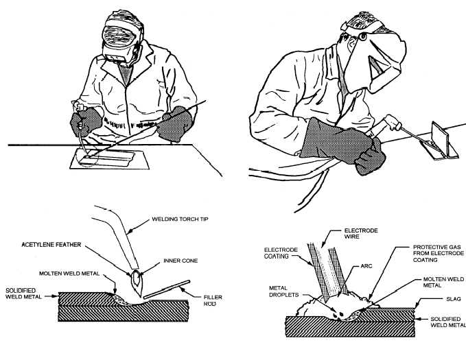
One of the most common types of arc welding is shielded metal arc welding ; it is also known as manual metal arc welding or stick welding.

Processes


Electric current is used to strike an arc between the base material and consumable electrode rod, which is made of filler material and is covered with a flux that protects the weld area from oxidation and contamination by producing carbon dioxide gas during the welding process.
Weld times are rather slow, since the consumable electrodes must be frequently replaced and because slag, the residue from the flux, must be chipped away after welding. Furthermore, the process is generally limited to welding ferrous materials, though special electrodes have made possible the welding of cast iron , nickel , aluminum, copper , and other metals.
Gas metal arc welding , also known as metal inert gas or MIG welding, is a semi-automatic or automatic process that uses a continuous wire feed as an electrode and an inert or semi-inert gas mixture to protect the weld from contamination.
A related process, flux-cored arc welding , uses similar equipment but uses wire consisting of a steel electrode surrounding a powder fill material. This cored wire is more expensive than the standard solid wire and can generate fumes and/or slag, but it permits even higher welding speed and greater metal penetration.
Gas tungsten arc welding , or tungsten inert gas welding, is a manual welding process that uses a nonconsumable tungsten electrode, an inert or semi-inert gas mixture, and a separate filler material.
Especially useful for welding thin materials, this method is characterized by a stable arc and high quality welds, but it requires significant operator skill and can only be accomplished at relatively low speeds.
Submerged arc welding is a high-productivity welding method in which the arc is struck beneath a covering layer of flux. This increases arc quality, since contaminants in the atmosphere are blocked by the flux.

Gas welding

It is one of the oldest and most versatile welding processes, but in recent years it has become less popular in industrial applications. The flame, since it is less concentrated than an electric arc, causes slower weld cooling, which can lead to greater residual stresses and weld distortion, though it eases the welding of high alloy steels.

http://img.ehowcdn.com/article-new/ehow/images/a06/t4/br/types-flames-gas-welding-1.1-800x800.jpg

Resistance


A specialized process, called shot welding , can be used to spot weld stainless steel. Like spot welding, seam welding relies on two electrodes to apply pressure and current to join metal sheets. However, instead of pointed electrodes, wheel-shaped electrodes roll along and often feed the workpiece, making it possible to make long continuous welds.

Energy beam


Energy beam welding methods, namely laser beam welding and electron beam welding , are relatively new processes that have become quite popular in high production applications.
Developments in this area include laser-hybrid welding , which uses principles from both laser beam welding and arc welding for even better weld properties, laser cladding and X-ray welding .
Solid-state Like the first welding process, forge welding, some modern welding methods do not involve the melting of the materials being joined.

http://www.weldguru.com/images/fig6-14.gif
Other solid-state welding processes include friction welding , electromagnetic pulse welding , co-extrusion welding , cold welding , diffusion bonding , exothermic welding , high frequency welding , hot pressure welding , induction welding , and roll welding .
Many welding processes require the use of a particular joint design; for example, resistance spot welding, laser beam welding, and electron beam welding are most frequently performed on lap joints.
Other welding methods, like shielded metal arc welding, are extremely versatile and can weld virtually any type of joint.

Quality

Many distinct factors influence the strength of welds and the material around them, including the welding method, the amount and concentration of energy input, the weldability of the base material, filler material, and flux material, the design of the joint, and the interactions between all these factors.
The effects of welding on the material surrounding the weld can be detrimental—depending on the materials used and the heat input of the welding process used, the HAZ can be of varying size and strength.
The efficiency is dependent on the welding process used, with shielded metal arc welding having a value of 0.75, gas metal arc welding and submerged arc welding, 0.9, and gas tungsten arc welding, 0.8.
Shielded metal arc welding is also often used in underwater welding in the construction and repair of ships, offshore platforms, and pipelines, but others, such as flux cored arc welding and gas tungsten arc welding, are also common.
http://www.roadkillcustoms.com/hot-rods-rat-rods/welding/fig11-9.gif
Welding in space is also possible—it was first attempted in 1969 by Russian cosmonauts, when they performed experiments to test shielded metal arc welding, plasma arc welding, and electron beam welding in a depressurized environment.

Further testing of these methods was done in the following decades, and today researchers continue to develop methods for using other welding processes in space, such as laser beam welding, resistance welding, and friction welding.

History

In 1881–82 a Russian inventor Nikolai Benardos created the first electric arc welding method known as carbon arc welding , using carbon electrodes.
Arc welding was first applied to aircraft during the war as well, as some German airplane fuselages were constructed using the process. Also noteworthy is the first welded road bridge in the world, designed by Stefan Bryła of the Warsaw University of Technology in 1927, and built across the river Słudwia Maurzyce near Łowicz, Poland in 1929.
During the following decade, further advances allowed for the welding of reactive metals like aluminum and magnesium . This in conjunction with developments in automatic welding, alternating current, and fluxes fed a major expansion of arc welding during the 1930s and then during World War II.
Gas tungsten arc welding , after decades of development, was finally perfected in 1941, and gas metal arc welding followed in 1948, allowing for fast welding of non- ferrous materials but requiring expensive shielding gases.
Shielded metal arc welding was developed during the 1950s, using a flux-coated consumable electrode, and it quickly became the most popular metal arc welding process.
In 1957, the flux-cored arc welding process debuted, in which the self-shielded wire electrode could be used with automatic equipment, resulting in greatly increased welding speeds, and that same year, plasma arc welding was invented.
Other recent developments in welding include the 1958 breakthrough of electron beam welding, making deep and narrow welding possible through the concentrated heat source.

Trends

Depending on the process, equipment cost can vary, from inexpensive for methods like shielded metal arc welding and oxyfuel welding , to extremely expensive for methods like laser beam welding and electron beam welding.
To do this, welding procedures with high deposition rates can be selected, and weld parameters can be fine-tuned to increase welding speed.
In recent years, in order to minimize labor costs in high production manufacturing, industrial welding has become increasingly more automated, most notably with the use of robots in resistance spot welding and in arc welding.
In robot welding, mechanized devices both hold the material and perform the weld and at first, spot welding was its most common application, but robotic arc welding increases in popularity as technology advances.
Other key areas of research and development include the welding of dissimilar materials and new welding processes, such as friction stir, magnetic pulse, conductive heat seam, and laser-hybrid welding. Furthermore, progress is desired in making more specialized methods like laser beam welding practical for more applications, such as in the aerospace and automotive industries.
Without proper fusion to the base materials provided by sufficient arc time on the weld, a project inspector cannot ensure the effective diameter of the puddle weld therefore he or she cannot guarantee the published load capacities unless they witness the actual installation. This method of puddle welding is common in the United States and Canada for attaching steel sheets to bar joist and structural steel members.

Turbine blade

A turbine blade is the individual component which makes up the turbine section of a gas turbine. The blades are responsible for extracting energy from the high temperature, high pressure gas produced by the combustor.

http://www.shelmetcastings.com/image-files/turbineblade1.jpg
The high pressure turbine is connected by a single spool to the high pressure compressor , and the low pressure turbine is connected to the low pressure compressor by a second spool .
In a gas turbine engine, a single turbine section is made up of a disk or hub that holds many turbine blades.
The number of turbine stages varies in different types of engines, with high bypass ratio engines tending to have the most turbine stages.
The number of turbine stages can have a great effect on how the turbine blades are designed for each stage.
The high pressure turbine is exposed to the hottest, highest pressure, air, and the low pressure turbine is subjected to cooler, lower pressure air.
That difference in conditions leads the design of high pressure and low pressure turbine blades to be significantly different in material and cooling choices even though the aerodynamic and thermodynamic principles are the same.

http://www.daviddarling.info/images/wind_turbine_blades.gif
All three of these factors can lead to blade failures, which can destroy the engine, and turbine blades are carefully designed to resist those conditions.
Further processing methods like hot isostatic pressing improved the alloys used for turbine blades and increased turbine blade performance.
Most turbine blades are manufactured by investment casting . This process involves making a precise negative die of the blade shape that is filled with wax to form the blade shape.
The blades are coated with an TBC they will have, and then cooling holes are machined as needed, creating a complete turbine blade.
Another strategy to improving turbine blades and increasing their operating temperature, aside from better materials, is to cool the blades.
Impingement cooling is often used on certain areas of a turbine blade, like the leading edge, with standard convection cooling used in the rest of the blade.
The second major type of cooling is film cooling . This type of cooling works by pumping cool air out of the blade through small holes in the blade. This air creates a thin layer of cool air on the surface of the blade, protecting it from the high temperature air.

http://www.freepatentsonline.com/6533547-0-large.jpg
A United State Air Force program in the early 1970s funded the development of a turbine blade that was both film and convection cooled, and that method has become common in modern turbine blades.
Transpiration cooling, the third major type of cooling, is similar to film cooling in that it creates a thin film of cooling air on the blade, but it is different in that air is "leaked" through a porous shell rather than injected through holes. This type of cooling is effective at high temperatures as it uniformly covers the entire blade with cool air.