Tuesday, 17 September 2013

Rocket engine

One of the most amazing endeavors man has ever undertaken is the exploration of space. A big p­art of the amazement is the complexity. Space exploration is complicated because there are so many problems to solve and obstacles to overcome.

Rocket engines as a group have the highest exhaust velocities, are by far the lightest, but are the least propellant efficient of all types of jet engines.

Rocket engines are fundamentally different. Rocket engines are reaction engines. The basic principle driving a rocket engine is the famous Newtonian principle that "to every action there is an equal and opposite reaction." A rocket engine is throwing mass in one direction and benefiting from the reaction that occurs in the other direction as a result.

Principle of operation

 Rocket engines produce thrust by the expulsion of a high-speed fluid exhaust. This fluid is nearly always a gas which is created by high pressure (10-200 bar) combustion of solid or liquid propellants, consisting of fuel and oxidiser components, within a combustion chamber.
Rocket engines produce thrust by the expulsion of a high-speed fluid exhaust. This fluid is nearly always a gas which is created by high pressure (10-200 bar) combustion of solid or liquid propellants, consisting of fuel and oxidiser components, within a combustion chamber.
The fluid exhaust is then passed through a supersonic propelling nozzle which uses heat energy of the gas to accelerate the exhaust to very high speed, and the reaction to this pushes the engine in the opposite direction.
In rocket engines, high temperatures and pressures are highly desirable for good performance as this permits a longer nozzle to be fitted to the engine, which gives higher exhaust speeds, as well as giving better thermodynamic efficiency.

Numerical control programming or NC programming

In modern CNC systems, end-to-end component design is highly automated using computer-aided design (CAD) and computer-aided manufacturing (CAM) programs. The programs produce a computer file that is interpreted to extract the commands needed to operate a particular machine via a postprocessor, and then loaded into the CNC machines for production.

Numerical control (NC) is the automation of machine tools that are operated by abstractly programmed commands encoded on a storage medium, as opposed to controlled manually via handwheels or levers, or mechanically automated via cams alone
 
http://ncprogramming.files.wordpress.com/2009/09/tool-3.jpg
Complex parts can be quickly and accurately programmed, over an extensive range of component types, in Catia V5 and subsequently verified in Vericut.

https://blogger.googleusercontent.com/img/b/R29vZ2xl/AVvXsEiMP6wvEZTQqzIHe5GVR-u5-7LPbrgRyT0xzevA4LxH_cHyITDKnycjmmoEam9gXwakLSkN0wArDQdGT45zNWP38AGauS0GlsNjs9sZ8qRy0AkMxUvpGCx1N7HMNoJsFPf7tuyYOa5pz5it/s400/5.PNG
In modern CNC systems, end-to-end component design is highly automated using computer-aided design (CAD) and computer-aided manufacturing (CAM) programs. The programs produce a computer file that is interpreted to extract the commands needed to operate a particular machine via a postprocessor, and then loaded into the CNC machines for production.

http://www.futuretooldesign.com/images/cnc-main.gif
Within the numerical systems of CNC programming it is possible for the code generator to assume that the controlled mechanism is always perfectly accurate, or that accuracy tolerances are identical for all cutting or movement directions. This is not always a true condition of CNC tools. CNC tools with a large amount of mechanical backlash can still be highly accurate if the drive or cutting mechanism is only driven so as to apply cutting force from one direction, and all driving systems are pressed tight together in that one cutting direction.

Thursday, 8 August 2013

The Bugatti

In 1998, the Volkswagen Group purchased the trademark rights on the former car manufacturer Bugatti in order to revive the brand.

http://superchargr.webs.com/photos/Bugatti-Wallpaer/2006%2520Bugatti%2520Veyron%2520W16%25201280x960_06.jpg
The Bugatti Veyron is, by every measure, the world's most extreme production road car. It's the quickest to 60, has the highest top speed, and can absolutely dominate a track.

The Bugatti Veyron is a car built around an engine. Essentially, Bugatti made the decision to blow the doors off the supercar world by creating a 1,000-horsepower engine. Everything else follows from that resolution.

On 6 April 2013, Bugatti set the record for having the highest top speed of any roadster in the world with the Veyron Grand Sport Vitesse, reaching on average a top speed of 408.84 km/h (254.04 mph)

The Veyron weighs a hulking 4,160 lbs, but even its harshest critics admit its handling is surprisingly sharp. Gordon Murray, designer of the McLaren F1 was very skeptical of the Veyron during its development, but after driving the finished car, he conceded it is a "huge achievement."
http://www.hottunedcars.com/wp-content/uploads/2010/03/Bugatti-16C-Galibier-Saloon-images-23.jpg

The Veyron's brakes use cross drilled, radially vented carbon fibre reinforced silicon carbide (C/SiC) composite discs, manufactured by SGL Carbon, which have a much greater resistance to brake fade when compared with conventional cast iron discs.

Wednesday, 7 August 2013

Biofuel

Biofuels have been around as long as cars have. At the start of the 20th century, Henry Ford planned to fuel his Model Ts with ethanol, and early diesel engines were shown to run on peanut oil.
http://newscenter.lbl.gov/wp-content/uploads/BiofuelLifeCycle1.jpg

A biofuel is a fuel that uses energy from a carbon fixation.
Gasoline and diesel are actually ancient biofuels. But they are known as fossil fuels because they are made from decomposed plants and animals that have been buried in the ground for millions of years. Biofuels are similar, except that they're made from plants grown today.

Biodiesel is made from vegetable oils and animal fats. Biodiesel can be used as a fuel for vehicles in its pure form, but it is usually used as a diesel additive to reduce levels of particulates, carbon monoxide, and hydrocarbons from diesel-powered vehicles. 
Much of the gasoline in the United States is blended with a biofuel—ethanol. This is the same stuff as in alcoholic drinks, except that it's made from corn that has been heavily processed. There are various ways of making biofuels, but they generally use chemical reactions, fermentation, and heat to break down the starches, sugars, and other molecules in plants. The leftover products are then refined to produce a fuel that cars can use.

http://www.agricorner.com/wp-content/uploads/2011/02/biofuel-ethanol.jpg
In 2010,worldwide biofuel production reached 105 billion liters (28 billion gallons US), up 17% from 2009, and biofuels provided 2.7% of the world's fuels for road transport, a contribution largely made up of ethanol and biodiesel. Global ethanol fuel production reached 86 billion liters (23 billion gallons US) in 2010, with the United States and Brazil as the world's top producers, accounting together for 90% of global production.

Biodiesel is the most common biofuel in Europe. It is produced from oils or fats using transesterification and is a liquid similar in composition to fossil/mineral diesel.

http://riotimesonline.com/wp-content/uploads/2010/02/biofuel_pump.jpg

Biofuel development in India centers mainly around the cultivation and processing of Jatropha plant seeds which are very rich in oil (40%). The drivers for this are historic, functional, economic, environmental, moral and political.

Friday, 26 July 2013

Thrust

In mechanical engineering, force orthogonal to the main load (such as in parallel helical gears) is referred to as thrust.

A motorboat generates thrust (or reverse thrust) when the propellers are turned to accelerate water backwards (or forwards). The resulting thrust pushes the boat in the opposite direction to the sum of the momentum change in the water flowing through the propeller.


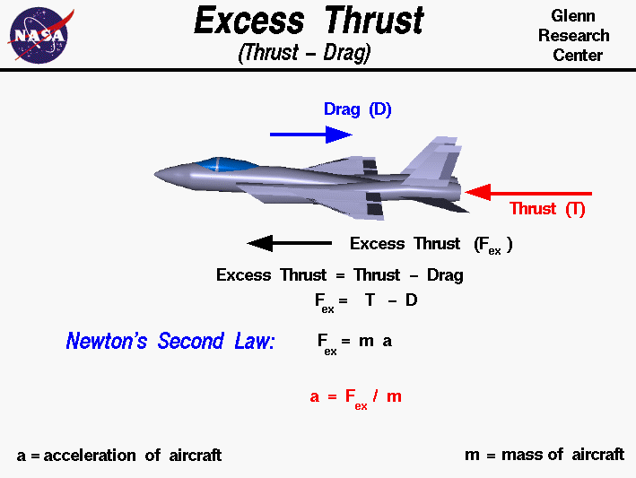
Thrust is the force which moves an aircraft through the air. Thrust is used to overcome the drag of an airplane, and to overcome the weight of a rocket. Thrust is generated by the engines of the aircraft through some kind of propulsion system.

A jet engine has no propeller, so the propulsive power of a jet engine is determined from its thrust as follows. Power is the force (F) it takes to move something over some distance (d) divided by the time (t) it takes to move that distance
\mathbf{P}=\mathbf{F}\frac{d}{t}
In case of a rocket or a jet aircraft, the force is exactly the thrust produced by the engine. If the rocket or aircraft is moving at about a constant speed, then distance divided by time is just speed, so power is thrust times speed
\mathbf{P}=\mathbf{T}{v}


Sunday, 21 July 2013

Spark Plug

The spark plug is quite simple in theory: It forces electricity to arc across a gap, just like a bolt of lightning. The electricity must be at a very high voltage in order to travel across the gap and create a good spark. Voltage at the spark plug can be anywhere from 40,000 to 100,000 volts.
http://www.2carpros.com/images/articles/engine/maintenance/tune_up/spark_plugs/how_to_gap_a_spark_plug.jpg
Spark plugs may also be used for other purposes; in Saab Direct Ignition when they are not firing, spark plugs are used to measure ionization in the cylinders - this ionic current measurement is used to replace the ordinary cam phase sensor, knock sensor and misfire measurement function. Spark plugs may also be used in other applications such as furnaces wherein a combustible fuel/air mixture must be ignited. In this case, they are sometimes referred to as flame igniters.
http://static.ddmcdn.com/gif/change-spark-plugs-1.jpg

Operation::

http://www.ngk.de/uploads/tx_templavoila/ngk_einbaulage_zuendkerzen_en_01.jpg
The plug is connected to the high voltage generated by an ignition coil or magneto. As the electrons flow from the coil, a voltage difference develops between the central electrode and side electrode. No current can flow because the fuel and air in the gap is an insulator, but as the voltage rises further, it begins to change the structure of the gases between the electrodes. Once the voltage exceeds the dielectric strength of the gases, the gases become ionized. The ionized gas becomes a conductor and allows electrons to flow across the gap. Spark plugs usually require voltage of 12,000–25,000 volts or more to 'fire' properly, although it can go up to 45,000 volts. They supply higher current during the discharge process resulting in a hotter and longer-duration spark.

Wednesday, 22 May 2013

Jet pack


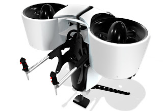
Jet pack, rocket belt, rocket pack and similar names are used for various types of devices, usually worn on the back, that are propelled by jets of escaping gases (or in some cases liquid water) so as to allow a single user to fly.
The concept emerged from science fiction in the 1920s and became popular in the 1960s as the technology became a reality. The most common use of the jet pack has been in extra-vehicular activities for astronauts. Despite decades of advancement in the technology, the challenges of Earth's atmosphere, Earth's gravity, and the fact that the human body is not adapted to fly naturally remain an obstacle to its potential use in the military or as a means of personal transport.


Powerhouse Productions Rocketbelt

More commonly known as "The Rocketman", Powerhouse Productions, owned and operated by Kinnie Gibson, is the first company to manufacture the 30 second flying Rocketbelt (June 1994) and to exclusively organize Rocketbelt performances. Since 1983 Powerhouse Productions has performed over show flights in over 40 countries such as the Carnival in Rio de Janerio, Super Bowls, the Rose Parade, Daytona 500, and the Michael jackson Dangerous World Tour, as well as many television shows including Walker Texas Ranger, The Fall Guy and NCIS. Powerhouse Rocketbelt pilots include stuntman Kinnie Gibson and Dan Schlund.

Turbojet pack

Packs with a turbojet engine are fueled with traditional kerosene. They have higher efficiency, greater height and a duration of flight of many minutes, but they are complex in construction and very expensive. Only one working model of this pack was made; it underwent flight tests in the 1960s and at present it no longer flies.

NASA's Manned Maneuvering Unit (MMU) (compressed gas powered)

In the 1980s, NASA demonstrated the Manned Maneuvering Unit (MMU), a rocket pack that allowed an astronaut to function as his/her own spacecraft, but the system was retired before the decade was over. The MMU is the only jet pack of practical importance. Its operational area is outside a space station or spacecraft, where an astronaut can limitedly move independently. The MMU's propulsion was produced by high-pressure nitrogen gas discharged through nozzles (of which the MMU has 24). The MMU was used after 1984 in three Space Shuttle missions

Sunday, 10 March 2013

Spark-ignition engine

The term spark ignition is used to describe the system with which the air-fuel mixture inside the combustion chamber of an internal combustion engine is ignited by a spark.
It is a process that uses an electrical field induced in a magneto or coil. The field builds to many thousands of volts and then is collapsed via a timed circuit. The resulting surge of current travels along a wire and terminates at the spark plug inside the combustion chamber. An electrical spark occurs as the charge tries to jump the precision gap at the tip of the spark plug at exactly the moment a precisely metered mixture of fuel and air has been thoroughly compressed in the combustion chamber. The resulting controlled explosion delivers the power to turn the reciprocating mass inside the engine.

http://www.networlddirectory.com/images/blogs/7-2007/fuel-efficient-engines-17981.jpg

Fuels

Spark-ignition engines are commonly referred to as "gasoline engines" in America, and "petrol engines" in Britain and the rest of the world. However, these terms are not preferred, since spark-ignition engines can (and increasingly are) run on fuels other than petrol/gasoline, such as autogas (LPG), methanol, ethanol, bioethanol, compressed natural gas (CNG), hydrogen, and (in drag racing) nitromethane.
http://www.synlube.com/images/eng4sglsw.jpg


Working cycle

https://blogger.googleusercontent.com/img/b/R29vZ2xl/AVvXsEgIp_WprgOcNWzisYCqk9UC6Q491e5QVliyLQzzQnpsLp8jjvsw-2lSbv9-zETxagyEatjPpZnYoThm93ShECMhVPoXHQCBWhbQpvWhszjBiCzYAH2ZvdVCtJg23PNfDkQerD3IFYbgIkw/s1600/image997.gif
A four-stroke spark-ignition engine is an Otto cycle engine. It consists of following four strokes: suction or intake stroke, compression stroke, expansion or power stroke, exhaust stroke. Each stroke consists of 180 degree rotation of crankshaft rotation and hence a four-stroke cycle is completed through 720 degree of crank rotation. Thus for one complete cycle there is only one power stroke while the crankshaft turns by two revolutions.

Monday, 4 March 2013

IC Engines

The internal combustion engine converts chemical energy into useful mechanical energy by burning fuel. Chemical energy is released when the fuel-air mixture is ignited by the spark in the combustion chamber. The gas produced in this reaction rapidly expands forcing the piston down the cylinder on the power stroke.
http://upload.wikimedia.org/wikipedia/commons/1/10/IC_engine.JPG
    The force is applied typically to pistons, turbine blades, or a nozzle. This force moves the component over a distance, transforming chemical energy into useful mechanical energy. The first commercially successful internal combustion engine was created by Étienne Lenoir.
http://burhanmech.webs.com/IC_engine_cam_crank_fourstorke-animation.gif
The piston reciprocates inside the cylinder, exhaust and intake ports open and close during various stages of the cycle. The movement of the piston up or down the cylinder makes up one stroke of the four stroke cycle (Otto cycle). The linear motion is then converted to rotary motion by the crankshaft. The crankshaft is shaped to balance the pistons which are fired in a particular order to reduce engine vibration (typically for a 4-cylinder engine, 1-2-4-3 or 1-3-4-2). The flywheel then helps smooth out the linear movement of the pistons.
https://blogger.googleusercontent.com/img/b/R29vZ2xl/AVvXsEi2mnctsoGMgs5zPOINWtzeFIx70eSImt14tjvKCIRM8arj_Z2n6E5rkvBQwoFW80GXoHGpJR2DdztpcxOvCUj3T7TcI5ebvS4ftGfBBOQdu0GbT71il20ibcnQYSWsjPlnijq5n7PdsCI/s1600/PetrolEngine.jpg
The ICE is quite different from external combustion engines, such as steam or Stirling engines, in which the energy is delivered to a working fluid not consisting of, mixed with, or contaminated by combustion products. Working fluids can be air, hot water, pressurized water or even liquid sodium, heated in some kind of boiler. ICEs are usually powered by energy-dense fuels such as gasoline or diesel, liquids derived from fossil fuels. While there are many stationary applications, most ICEs are used in mobile applications and are the dominant power supply for cars, aircraft, and boats. 

Types of internal combustion engine

Reciprocating:
  • Two-stroke engine
  • Four-stroke engine (Otto cycle)
  • Six-stroke engine
  • Diesel engine
  • Atkinson cycle
  • Miller cycle
Rotary:
  • Wankel engine
Continuous combustion:


  • http://studyvilla.com/Images/icengines9.gif

    • Gas turbine
    • Jet engine (including turbojet, turbofan, ramjet, Rocket, etc.)

    Two-stroke configuration

    Engines based on the two-stroke cycle use two strokes (one up, one down) for every power stroke. Since there are no dedicated intake or exhaust strokes, alternative methods must be used to scavenge the cylinders. The most common method in spark-ignition two-strokes is to use the downward motion of the piston to pressurize fresh charge in the crankcase, which is then blown through the cylinder through ports in the cylinder walls.

    Spark-ignition two-strokes are small and light for their power output and mechanically very simple; however, they are also generally less efficient and more polluting than their four-stroke counterparts. In terms of power per cm³, a two-stroke engine produces comparable power to an equivalent four-stroke engine.
    http://www.chooseindia.com/engineering/img/two-stroke-parts.gif

    Four-stroke

    Engines based on the four-stroke ("Otto cycle") have one power stroke for every four strokes (up-down-up-down) and employ spark plug ignition. Combustion occurs rapidly, and during combustion the volume varies little ("constant volume"). They are used in cars, larger boats, some motorcycles, and many light aircraft. They are generally quieter, more efficient, and larger than their two-stroke counterparts.
    The steps involved here are:
    1. Intake stroke: Air and vaporized fuel are drawn in.
    2. Compression stroke: Fuel vapor and air are compressed and ignited.
    3. Combustion stroke: Fuel combusts and piston is pushed downwards.
    4. Exhaust stroke: Exhaust is driven out. During the 1st, 2nd, and 4th stroke the piston is relying on power and the momentum generated by the other pistons. In that case, a four-cylinder engine would be less powerful than a six- or eight-cylinder engine.
     

    Sunday, 3 March 2013

    Turbo engines

    When people talk about race cars or high-performance sports cars, the topic of turbochargers usually comes up. Turbochargers also appear on large diesel engines. A turbo can significantly boost an engine's horsepower without significantly increasing its weight, which is the huge benefit that makes turbos so popular

    http://www.bhptuning.com/assets/images/engine_1.8t_small.jpg
    A turbo-compound engine is a reciprocating engine that employs a blowdown turbine to recover energy from the exhaust gases. The turbine is usually mechanically connected to the crankshaft, as on the DC-7B and the Super Constellation, but electric and hydraulic systems have been investigated as well. The turbine increases the output of the engine without increasing its fuel consumption, thus reducing the specific fuel consumption. The turbine is referred to as a "blowdown turbine" , as it recovers the energy developed in the exhaust manifold during blowdown, that is the first period of the exhaust process when the piston still is on its expansion stroke.

    http://upload.wikimedia.org/wikipedia/commons/2/2c/Porsche_935_Bi-Turbo_engine_TCE.jpg
    The first aircraft engine to be tested with a power-recovery turbine was the Rolls-Royce Crecy, during WWII. This was used primarily to drive a geared centrifugal supercharger, although it was also coupled to the crankshaft and gave an extra 15 to 35 percent fuel economy.

    http://www.smreperformance.com/images/turbo-engine-package.gif
    In order to achieve this boost, the turbocharger uses the exhaust flow from the engine to spin a turbine, which in turn spins an air pump. The turbine in the turbocharger spins at speeds of up to 150,000 rotations per minute (rpm) -- that's about 30 times faster than most car engines can go. And since it is hooked up to the exhaust, the temperatures in the turbine are also very high.

    Friday, 1 March 2013

    Casting

    Casting processes have been known for thousands of years, and widely used for sculpture, especially in bronze, jewellery in precious metals, and weapons and tools. Traditional techniques include lost-wax casting, plaster mold casting and sand casting.
    The modern casting process is subdivided into two main categories: expendable and non-expendable casting. 
    http://www.jepsculpture.com/art/ben-casting.jpg

    Expendable mold casting

    1. Sand casting

      Sand casting is one of the most popular and simplest types of casting that has been used for centuries. Sand casting allows for smaller batches to be made compared to permanent mold casting and at a very reasonable cost.

      Sand casting requires a lead time of days for production at high output rates (1–20 pieces/hr-mold) and is unsurpassed for large-part production. Green (moist) sand has almost no part weight limit, whereas dry sand has a practical part mass limit of 2,300–2,700 kg (5,100–6,000 lb). Minimum part weight ranges from 0.075–0.1 kg (0.17–0.22 lb). The sand is bonded together using clays, chemical binders, or polymerized oils (such as motor oil). Sand can be recycled many times in most operations and requires little maintenance.
      http://www.efunda.com/processes/metal_processing/images/casting_main.gif


      Plaster mold casting

      Plaster casting is an inexpensive alternative to other molding processes for complex parts due to the low cost of the plaster and its ability to produce near net shape castings. The biggest disadvantage is that it can only be used with low melting point non-ferrous materials, such as aluminium, copper, magnesium, and zinc.

      Shell molding

      http://www.custompartnet.com/wu/images/investment-casting/investment-casting.png
      Shell molding is similar to sand casting, but the molding cavity is formed by a hardened "shell" of sand instead of a flask filled with sand. The sand used is finer than sand casting sand and is mixed with a resin so that it can be heated by the pattern and hardened into a shell around the pattern.


      Non-expendable mold casting

      Non-expendable mold casting differs from expendable processes in that the mold need not be reformed after each production cycle. This technique includes at least four different methods: permanent, die, centrifugal, and continuous casting.

      Permanent mold casting

      Permanent mold casting is a metal casting process that employs reusable molds ("permanent molds"), usually made from metal. The most common process uses gravity to fill the mold, however gas pressure or a vacuum are also used. A variation on the typical gravity casting process, called slush casting, produces hollow castings.

      Die casting

        Most die castings are made from nonferrous metals, specifically zinc, copper, and aluminium based alloys, but ferrous metal die castings are possible. The die casting method is especially suited for applications where many small to medium sized parts are needed with good detail, a fine surface quality and dimensional consistency.
      http://www.enproinc.com/wps/wcm/connect/177191004f03a6bab1a7b1a2d23b7e5e/diecasting.jpg?MOD=AJPERES&CACHEID=177191004f03a6bab1a7b1a2d23b7e5e


      Terminology 

      Flask: The rigid wood or metal frame that holds the molding material.
      Cope: The top half of the pattern, flask, mold, or core.
      Drag: The bottom half of the pattern, flask, mold, or core.
      Core: An insert in the mold that produces internal features in the casting, such as holes.

      Core print: The region added to the pattern, core, or mold used to locate and support the core.
      Mold cavity: The combined open area of the molding material and core, there the metal is poured to produce the casting.
      Riser: An extra void in the mold that fills with molten material to compensate for shrinkage during solidification.
      Gating system: The network of connected channels that deliver the molten material to the mold cavities.
      Draft: The taper on the casting or pattern that allow it to be withdrawn from the mold
      Core box: The mold or die used to produce the cores.


    Tuesday, 26 February 2013

    Catalytic converter

    What is a catalytic converter and how does it work? 

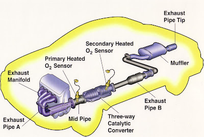
    A catalytic converter is a device that uses a catalyst to convert three harmful compounds in car exhaust into harmless compounds.

    The three harmful compounds are:
    • Hydrocarbons (in the form of unburned gasoline)
    • Carbon monoxide (formed by the combustion of gasoline)
    • Nitrogen oxides (created when the heat in the engine forces nitrogen in the air to combine with oxygen)
    http://static.ddmcdn.com/gif/catalytic-converter-location.jpg
    Carbon monoxide is a poison for any air-breathing animal. Nitrogen oxides lead to smog and acid rain, and hydrocarbons produce smog.
    In a catalytic converter, the catalyst (in the form of platinum and palladium) is coated onto a ceramic honeycomb or ceramic beads that are housed in a muffler-like package attached to the exhaust pipe. The catalyst helps to convert carbon monoxide into carbon dioxide. It converts the hydrocarbons into carbon dioxide and water. It also converts the nitrogen oxides back into nitrogen and oxygen.

    http://www.cateran.com.au/cateran/images/technical.jpg
    Most commonly used in an automobile's exhaust system, catalytic converters are now commonly used on generator sets, forklifts, mining equipment, trucks, buses, trains, and other machines that have engines to provide an environment for a chemical reaction where unburned hydrocarbons are more completely combusted.

    http://completeautomotive417.com/wp-content/uploads/2011/08/Catalytic_Converter.jpg.opt677x480o00s677x480.jpg
    Catalytic converters are still most commonly used in exhaust systems in automobiles, but are also used on generator sets, forklifts, mining equipment, trucks, buses, locomotives, motorcycles, airplanes and other engine-fitted devices.

    Types

    Two-way

    A two-way (or "oxidation") catalytic converter has two simultaneous tasks:
    1. Oxidation of carbon monoxide to carbon dioxide: 2CO + O2 → 2CO2
    2. Oxidation of hydrocarbons (unburnt and partially burnt fuel) to carbon dioxide and water: CxH2x+2 + [(3x+1)/2] O2 → xCO2 + (x+1) H2O (a combustion reaction)
    This type of catalytic converter is widely used on diesel engines to reduce hydrocarbon and carbon monoxide emissions. They were also used on gasoline engines in American- and Canadian-market automobiles until 1981. Because of their inability to control oxides of nitrogen, they were superseded by three-way converters.

    http://autotech4rent.com/home/wp-content/uploads/2011/11/catalytic-photo.jpg

    Three-way

    Since 1981, "three-way" (oxidation-reduction) catalytic converters have been used in vehicle emission control systems in the United States and Canada; many other countries have also adopted stringent vehicle emission regulations that in effect require three-way converters on gasoline-powered vehicles. The reduction and oxidation catalysts are typically contained in a common housing, however in some instances they may be housed separately. A three-way catalytic converter has three simultaneous tasks:
    https://blogger.googleusercontent.com/img/b/R29vZ2xl/AVvXsEgIyqng0GF0iIeFgP0qSDYoTwypA_S8kZAAsxEfPHC34O2I07Q1h_Z4Q7MAvDCopAXwNaLOFtXSOmrtBguNdklo4tYj27vrIP3IBxvwAQahr-1VNlQf0Hdr4xdg9lB7tipbM6IoSqBI0kuX/s1600/catalytic+converter.jpg
    1. Reduction of nitrogen oxides to nitrogen and oxygen: 2NOx → xO2 + N2
    2. Oxidation of carbon monoxide to carbon dioxide: 2CO + O2 → 2CO2
    3. Oxidation of unburnt hydrocarbons (HC) to carbon dioxide and water: CxH2x+2 + [(3x+1)/2]O2 → xCO2 + (x+1)H2O.

    Actuator

    An actuator is something that converts energy into motion. It also can be used to apply a force. An actuator typically is a mechanical device that takes energy — usually energy that is created by air, electricity or liquid — and converts it into some kind of motion. That motion can be in virtually any form, such as blocking, clamping or ejecting. Actuators typically are used in manufacturing or industrial applications and might be used in devices such as motors, pumps, switches and valves.
    Perhaps the most common type of actuator is powered b
    y air and is called a pneumatic cylinder or air cylinder. 
    http://www.spiraxsarco.com/images/resources/steam-engineering-tutorials/6/6/fig6.6.01.gif
    An actuator also can be powered by electricity or hydraulics. Much like there are air cylinders, there also are electric cylinders and hydraulic cylinders in which the cylinder converts electricity or hydraulics into motion. Hydraulic cylinders, which use liquids, are often found in certain types of vehicles.
    . An actuator is the mechanism by which a control system acts upon an environment. The control system can be simple (a fixed mechanical or electronic system), software-based (e.g. a printer driver, robot control system), or a human or other agent.

    http://www.wordsun.com/assets/raw-2-1184330585.jpg

    Types of Motion

    Actuators can create a linear motion, rotary motion or oscillatory motion. That is, they can create motion in one direction, in a circular motion or in opposite directions at regular intervals. Hydraulic and air cylinders can be classified as single-acting cylinders, meaning that the energy source causes movement in one direction and a spring is used for the other direction.
    http://www.mathworks.com/help/physmod/hydro/ref/dbl_act_valve_act2.gif
                                                          HYDRAULIC ACTUATORS

    Muscles as Actuators

    Although actuators typically are discussed in terms of mechanical implements, muscles are sometimes given as an example of actuators. Energy is converted by the muscle into motion. For example, the calories that are in food that a person consumes represent energy that can be used by his or her muscles — which act as actuators — to create motion, such as running, kicking a ball or dancing.

    Sensors AND Transducers

    Sensors can be broadly classified in two categories: discrete event and continuous. Discrete event, or on/off sensor, changes its state based on the occurrence of some external event. These sensors typically only give knowledge of two states based on the condition being sensed. They are based on mechanical, electrical or optical technology. Continuous sensors provide information over the continuous range of operation of the process and are commonly used in continuous control applications, where the process is being regulated based on continuously sensed attribute data. They are based on electrical, optical and acoustical technologies.
    http://www.opengeospatial.org/pub/www/files/images/SWE%20Overview_0.jpg

    ACTIVE AND PASSIVE SENSORS

    The sensors can be classified as active and passive. A passive sensor has no power supply and all the energy it delivers to the next stage (the signal conditioning) is drawn from the measurand. Passive sensors are also known as self-generating sensors. An active sensor is a modulator and can therefore deliver more energy to the next stage than it draws from the measurand. If the power supply is dc, the output is modulated by the measurand, and has the same frequency. If the supply is ac, the output is the carrier frequency with sidebands at signal frequency.
    https://blogger.googleusercontent.com/img/b/R29vZ2xl/AVvXsEhUFtGCOuHW9tU2vtTEYRtKBGdn1oMrWYcM6PocuuAyW1nEFgY8a-U3rgzAPlHNpePfuOowgOqtWOzVUFAICDbqwgL05u7c4v5Bf8Qq8d8sox2Q9ojNH1Zigk4wWHdyCcEUibFcoZsmzsc/s1600/Capacitor+Pressure+Transducer.JPG

    BASIC REQUIREMENTS OF A SENSOR/TRANSDUCER

    A transducer is normally designed to sense a specific measurand or to respond only to that
    particular measurand. A complete knowledge of the electrical and mechanical
    characteristics of the transducer is of great importance while choosing a transducer for a
    particular application. Often, it is deemed essential to get details of these characteristics
    during the selection of instrumentation for the experiment concerned. The basic
    requirements are : 

    Ruggedness

    Ability to withstand overloads, with safety stops for overload protection.

     Linearity

    Ability to reproduce input-output characteristics symmetrically and linearly.
    Overall linearity is the main factor considered.

     Repeatability

    Ability to reproduce the output signal exactly when the same measurand is
    applied repeatedly under same environmental conditions.

     Convenient Instrumentation

    Sufficiently high analog output signal with high signal to noise ratio; digital

    TRANSDUCERS

    A useful way to classify transducers is on the basis of the physical property the device is intended to measure. The important properties discussed in this section are :
     Position
     Velocity
     Force or Pressure
     Temperature

     Position Transducers

    Position transducers are widely used in servomotors, linear position tables, and other applications where prices position is important. In this section we will discuss four analog position transducers (potentiometers, linear variable differential transformers, floats and resolvers) and two digital position transducers (the optical encoder and ultrasonic range sensor).
    http://www.puiaudio.com/images/whitepaper_transducer_circuit1.jpg

    Velocity Transducers

    Velocity transducers are used for speed control. We shall describe the digital (optical
    encoder) and analog (DC tachometer) velocity transducers.
    Force or Pressure Transducers
    Force sensors are used extensively in automatic weighing operation in the process
    industries and in robotic applications when it is necessary to control gripping pressure. In
    this section we shall examine two analog transducers: the load cell and the strain gage.

    Load Cells

    A load cell is used in processes where precise weighing is required. It can be
    implemented using a strain gage or a LVDT. Illustrates a load cell
    implemented by using a LVDT and a spring with linear force displacement relation.

    Electromagnetic clutches

    Electromagnetic clutches and brakes seem simple, but complex variations fit them to multiple applications.

    Electromagnetic clutches operate electrically but transmit torque mechanically. Engineers once referred to them as electromechanical clutches. Over the years EM came to stand for electromagnetic, referring to the way the units actuate, but their basic operation has not changed.
    The electromagnetic clutch is most suitable for remote operation since no linkages are required to control its engagement. It has fast, smooth operation. However, because energy dissipates as heat in the electromagnetic actuator every time the clutch is engaged, there is a risk of overheating.
    http://magnetic-clutch.com/assets/images/clutch-internal.jpg


    Elements of EM
    Both EM clutches and brakes share basic structural components: a coil in a shell, also referred to as a field; a hub; and an armature. A clutch also has a rotor, which connects to the moving part of the machine, such as a driveshaft.
    The coil shell is usually carbon steel, which combines strength with magnetic properties. Copper wire forms the coil, although sometimes aluminum is used. A bobbin or epoxy adhesive holds the coil in the shell.
    Magnetic and friction forces accelerate the armature and hub to match rotor speed. The rotor and armature slip past each other for the first 0.02 to 1.0 sec until the input and output speeds are the same. The matching of speeds is sometimes called 100% lockup.

    How it works

    Engagement

    When the clutch is required to actuate, current flows through the electromagnet, which produces a magnetic field. The rotor portion of the clutch becomes magnetized and sets up a magnetic loop that attracts the armature. The armature is pulled against the rotor and a frictional force is generated at contact. Within a relatively short time, the load is accelerated to match the speed of the rotor, thereby engaging the armature and the output hub of the clutch.

    Disengagement

    When current is removed from the clutch, the armature is free to turn with the shaft. In most designs, springs hold the armature away from the rotor surface when power is released, creating a small air gap.
    http://upload.wikimedia.org/wikipedia/commons/5/54/B-1_electromagnetic-clutch1.gif

    Cycling

    Cycling is achieved by interrupting the current through the electromagnet. Slippage normally occurs only during acceleration. When the clutch is fully engaged, there is no relative slip, assuming the clutch is sized properly, and thus torque transfer is 100% efficient.

    Applications

    Machinery
    Automobiles
    Locomotives

    Applications in automobile

    When the electromagnetic clutch is used in automobiles, there may be a clutch release switch inside the gear lever. The driver operates the switch by holding the gear lever to change the gear, thus cutting off current to the electromagnet and disengaging the clutch. With this mechanism, there is no need to depress the clutch pedal. Alternatively, the switch may be replaced by a touch sensor or proximity sensor which senses the presence of the hand near the lever and cuts off the current. The advantages of using this type of clutch for automobiles are that complicated linkages are not required to actuate the clutch, and the driver needs to apply a considerably reduced force to operate the clutch. It is a type of semi-automatic transmission.

    Monday, 25 February 2013

    steering system

    You know that when you turn the steering wheel in your car, the wheels turn. Cause and effect, right? But a lot of interesting stuff goes on between the steering wheel and the tires to make this happen.
    In this article, we'll see how the two most common types of c­ar steering systems work: rack-and-pinion and recirculating-ball steering. Then we'll examine power steering and find out about some interesting future developments in steering systems, driven mostly by the need to increase the fuel efficiency of cars.


    http://fireonroad.com/wp-content/uploads/2013/01/STEERING-SYSTEM.jpg

    Introduction

    Steering is the term applied to the collection of components, linkages, etc. which will allow a vessel (ship, boat) or vehicle to follow the desired course.

    Wheeled vehicle steering

    The basic aim of steering is to ensure that the wheels are pointing in the desired directions. This is typically achieved by a series of linkages, rods, pivots and gears. One of the fundamental concepts is that of caster angle - each wheel is steered with a pivot point ahead of the wheel; this makes the steering tend to be self-centering towards the direction of travel.
    http://fireonroad.com/wp-content/uploads/2013/01/Parts-of-the-Steering-System.gif


    Rack and pinion

    The rack and pinion design has the advantages of a large degree of feedback and direct steering "feel". A disadvantage is that it is not adjustable, so that when it does wear and develop lash, the only cure is replacement.

    http://www.monroe.com.au/uploads/images/tech_info_images/Steering%20Systems3.gif


    The recirculating ball version of this apparatus reduces the considerable friction by placing large ball bearings between the teeth of the worm and those of the screw; at either end of the apparatus the balls exit from between the two pieces into a channel internal to the box which connects them with the other end of the apparatus, thus they are "recirculated".
    https://blogger.googleusercontent.com/img/b/R29vZ2xl/AVvXsEhgMf0hnbX7w2tNQSuucxwVA5W2H03lgJMpLSqDxfRBvmSRCAne_cwigmmX-3dmeLhcM3Z7ak9hUo4hZ-8tr-8lFVbwEf2jTw-CoAgm_CSfmz6S2QRJfYRnR6C58Mx3JLXXe3VSqCN_fsir/s1600/steering.jpg
    The worm and sector was an older design, used for example in Willys and Chrysler vehicles, and the Ford Falcon (1960s).

    Power steering

    http://www.infovisual.info/05/img_en/073%20Hydraulic%20steering%20system.jpg
    Power steering helps the driver of a vehicle to steer by directing some of the its power to assist in swivelling the steered roadwheels about their steering axes. As vehicles have become heavier and switched to front wheel drive, particularly using negative offset geometry, along with increases in tire width and diameter, the effort needed to turn the wheels about their steering axis has increased, often to the point where major physical exertion would be needed were it not for power assistance.

    Four-wheel steering

    Four-wheel steering (or all-wheel steering) is a system employed by some vehicles to improve steering response, increase vehicle stability while maneuvering at high speed, or to decrease turning radius at low speed.

    http://firetrucksandequipment.tpub.com/TM-5-4210-220-12/img/TM-5-4210-220-12_28_1.jpg

    Crab steering

    Crab steering is a special type of active four-wheel steering. It operates by steering all wheels in the same direction and at the same angle. Crab steering is used when the vehicle needs to proceed in a straight line but under an angle (i.e. when moving loads with a reach truck, or during filming with a camera dolly), or when the rear wheels may not follow the front wheel tracks.

    Passive rear wheel steering

    Many modern vehicles offer a form of passive rear steering to counteract normal vehicle tendencies. On many vehicles, when cornering, the rear wheels tend to steer slightly to the outside of a turn, which can reduce stability. The passive steering system uses the lateral forces generated in a turn (through suspension geometry) and the bushings to correct this tendency and steer the wheels slightly to the inside of the corner. This improves the stability of the car, through the turn.

    Rear wheel steering

    ear wheel steering tends to be unstable because in turns the steering geometry changes hence decreasing the turn radius (oversteer), rather than increase it (understeer). A rear wheel steered automobile exhibits non-minimum phase behavior.
    http://www.hsomerville.com/meccano/images/4ws1.jpg

    Safety

    For safety reasons all modern cars feature a collapsible steering column (energy absorbing steering column) which will collapse in the event of a heavy frontal impact to avoid excessive injuries to the driver. Airbags are also generally fitted as standard. Non-collapsible steering columns fitted to older vehicles very often impaled drivers in frontal crashes, particularly when the steering box or rack was mounted in front of the front axle line, at the front of the crumple zone.

    Watercraft steering

    http://www.freepatentsonline.com/7156034-0-large.jpg
    Ships and boats are usually steered with a rudder. Depending on the size of the vessel, rudders can be manually actuated, or operated using a servomechanism, or a trim tab/servo tab system. Boats using outboard motors steer by rotating the entire drive unit. Boats with inboard motors sometimes steer by rotating the propeller pod only